I'm tired of the striped lines & was curious if I could pay/trade for anyone to do this mod for me.
I've never soldered a wire in my life & don't want to start practicing on my Toploader.


I'm tired of the striped lines & was curious if I could pay/trade for anyone to do this mod for me.
I've never soldered a wire in my life & don't want to start practicing on my Toploader.
We don't stop playing because we grow old; we grow old because we stop playing.
I have a toploader with the av mod, and you can still see the striped lines.
Dammit.
I thought that was what would fix the problem. So what's the advantage of an A/V mod? Stereo sound?
We don't stop playing because we grow old; we grow old because we stop playing.

I guess, and composite video is at least a little better than RF. The reason you're seeing those lines is because the unit supposedly doesn't have any metal shielding inside. I say supposedly because I never had one to open and see personally. Could try getting some tin flashing and shaping it to stick in there.

Some questions...
http://www.gamesx.com/rgbadd/nes2avmod.htm
I am about to start this AV mod (finally). I was unable to find 1.3k ohm resistors. Radio Shack recommended just putting a 1k and a 330 ohm in series, because they said it will be about the same, 1330 instead of 1300. Is this going to be a problem?
Also, I am looking at the pictures and in #2, is the red wire connected to the top or bottom solder spot near the end of the wire. It's hard to tell from the pic, but I think it is the upper one. Double checking. Also, in pic #3, is the ground wire connected to that solder point or to the side of it (not even sure if that makes sense)?
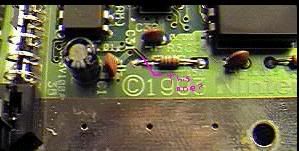
I see R3 which I am supposed to remove, and also remove the tracing underneath. Are they speaking of underneath as in the bottom of the board or the top of the board, directly underneath where the resistor was? Is the tracing the light green or the dark green? What am I supposed to cut. If it's the light green, from the underside it doesn't even appear as if they are connected. It's hard to tell with the top side. I see two dark green lines running underneath, with a light green line between, which I think is the trace.
Here's an edited version of the picture from the site. I have a pink line marking what I *think* is what I am to cut..
The resistors I bought were 1/2 Watt...if there's a problem with this also, let me know.
I F*CKING HATE THIS. I SHOULD HAVE PAID FOR SOMEONE TO MOD THIS INSTEAD OF PAYING $32 FOR A SOLDERING IRON, WIRE, SOLDER, THE PARTS, EVERYTHING ELSE AND STILL I DON'T KNOW THE HELL I AM DOING. YES, I'M FRUSTRATED .... *grumble*

*wispers* I think someone is cranky. *end wispers*
I am
I have an opened NES with screws laying everywhere and I want to get this done
I have three NES's, this is my only top loader one, and I don't want to ruin it as it's my only one that still works (the others are toasters and blink all the time...one I broke the pins when trying to refurb..).
I never heard that, got a link?Originally Posted by Bratwurst
The last theory I heard was that an internal signal was running at twice the frequency it did in a front loader. I've tried adding extra capacitance in different places but never got rid of it.
BTW, I'm taking these 1/2 Watters back and getting the 1/4 ones. Noticing how much space is inside...better go for the smaller ones.

Why bother puttin an A/V mod on a toploader?To make the vert lines sharper?
Spend your time fixin up a frontloader and keep your carts clean.
.......... hmmmm .... Well, he does make a VERY good point!....
Yes, it really does make more sense to use a toaster NES that does not get the lines that already has AV outputs. Much more sense indeed! That way you also do not risk ruining a perfectly good NES toploader as well!
Does Nintendo still give out pin connectors?
You mean the cart slot 72-pin connectors?
I do believe they do! Otherwise they are only 2 or 3 bucks on the web +shipping.

Yeah, seriously, top loaders are way over rated. It is far easier and cheaper to simply fix a toaster, and the end result is nicer.
Agreed!
 Posting Permissions
As an Amazon Associate I earn from qualifying purchases. Similar agreements apply to other advertising or affiliate programs such as those from eBay, Google, etc.
Copyright © 1991 - Present of Digital Press. All rights reserved.

 Reply With Quote