Page 1 of 2 12 LastLast
Results 1 to 20 of 21

Thread: Genny 2 Region mod gone bad, who wants it?

  1. #1
    Strawberry (Level 2) Lanzo's Avatar
    Join Date
    Apr 2010
    Location
    Youngstown, OH
    Posts
    442
    Thanks Thanks Given 
    0
    Thanks Thanks Received 
    0
    Thanked in
    0 Posts
    Xbox LIVE
    DT Maniac

    Default Genny 2 Region mod gone bad, who wants it?


    Bold is new stuff

    Some of you may remember when I posted this thread originally, just read through it to find out what happened. Any way I ended up breaking off the leg I needed to pry up completely meaning this system is beyond fixing or requires finer skills than I have. The system turns on and has a 50/60 htz switch that works, but both come in black and white. The game will play but you wont get very far as the the "Start""a, and b" buttons don't register in the first controller port because I bumped the leg next to the one I broke off which I believe I traced to the controller port. So before I toss this Im putting it up for grabs for anyone who wants to try and fix it. The shell is brand new besides the 2 holes drilled in the side.

    All in all If I tried this mod again I would do it different and def would not try it as my 3rd mod/time using a soldering iron but we learn from out mistakes. If you want it just pay shipping and its yours. Its a PAL Megadrive 2 and its pretty light (came with no metal shielding inside).


    Before you go like "why would you mod a model 2?" please read, lol. I have already modded my model 1 but I now have a brand new model 2 in the box and everthing, there is only one problem. It's a Pal Megadrive 2 (Asian). I know it can be modded as I have seen a tutorial http://www.mmmonkey.co.uk/console/sega/md2switches.htm (the motherboards are near identical) but how would this work if I did a 50/60 htz switch using an ntsc tv? I always see ntsc systems modded but not pal systems. Is something like this worth doing? Also the most important question before anything else is the power supply dilemma. The pal supply obviously won't plug into anything here but would I be able to use an American genny 2 power supply? Pal input 230 v - 50 htz, ntsc input 120 v - 60 htz. So, any ideas or advice from the experts? Or an opposite one of these http://cgi.ebay.com/Snes-NTSC-Pal-Po...item1e62f050b5
    Last edited by Lanzo; 09-21-2011 at 06:10 PM.

  2. #2
    Alex (Level 15) Custom rank graphic
    Gameguy's Avatar
    Join Date
    Dec 2008
    Location
    Richmond Hill, Ontario (Canada)
    Posts
    7,920
    Thanks Thanks Given 
    0
    Thanks Thanks Received 
    78
    Thanked in
    70 Posts

    Default

    Aren't PAL Asian systems rare? It might be worth more unmodded, especially since it's brand new in the box. I really can't remember if these are valuable, I think the Japanese Mega Drives are valuable but I'm not sure about the PAL Asian systems.

    I don't think the power supply would really be a problem, if you just use a North American supply with the console instead of the original one. What matters is the output of the power supplies, not so much the inputs(check the ratings listed on them).

  3. #3
    Strawberry (Level 2) Lanzo's Avatar
    Join Date
    Apr 2010
    Location
    Youngstown, OH
    Posts
    442
    Thanks Thanks Given 
    0
    Thanks Thanks Received 
    0
    Thanked in
    0 Posts
    Xbox LIVE
    DT Maniac

    Default

    Idk if they are rare, it's basically a pal system with JP shell, even the box is in Japanese, but there is a pal seal. Opening it up I thought it was interesting there was no metal shielding at all. I also have 2 of these systems because I thought one would be cool to keep unopened.

    I will try the power supplies tomorrow. I think it would be cool to have a universal megadrive 2. I really do wish it was NTSC though so I could jump right in!

  4. #4
    Alex (Level 15) InsaneDavid's Avatar
    Join Date
    Nov 2004
    Location
    Silicon Valley, USA
    Posts
    7,366
    Thanks Thanks Given 
    24
    Thanks Thanks Received 
    13
    Thanked in
    12 Posts

    Default

    What you start with really doesn't matter that much. If it has a 315-XXXX chip then pin 107 denotes USA/JPN and pin 46 denotes 50Hz/60Hz. Your system will simply be hardwired USA/50Hz to start.

  5. #5
    Pear (Level 6) Oldskool's Avatar
    Join Date
    Oct 2009
    Location
    Las Vegas
    Posts
    1,262
    Thanks Thanks Given 
    0
    Thanks Thanks Received 
    0
    Thanked in
    0 Posts

    Default

    Why not just use a Game Genie? Then you don't have to widen the slot and/or mod anything. There is a master list of Game Genie codes to region switch all the imports.

  6. #6
    Strawberry (Level 2) Lanzo's Avatar
    Join Date
    Apr 2010
    Location
    Youngstown, OH
    Posts
    442
    Thanks Thanks Given 
    0
    Thanks Thanks Received 
    0
    Thanked in
    0 Posts
    Xbox LIVE
    DT Maniac

    Default

    Quote Originally Posted by Oldskool View Post
    Why not just use a Game Genie? Then you don't have to widen the slot and/or mod anything. There is a master list of Game Genie codes to region switch all the imports.
    Idk, I have 2 game genies, this is more for fun to be honest I don't own a single import game, and as far as the slot I don't think I will need to widen it unless JP carts are bigger than eu carts. The slot on this one is def bigger than my American genny 2 slot. The only reason I won't mod that one is because it's my childhood genesis, sentimental value lol.

  7. #7
    Strawberry (Level 2) Lanzo's Avatar
    Join Date
    Apr 2010
    Location
    Youngstown, OH
    Posts
    442
    Thanks Thanks Given 
    0
    Thanks Thanks Received 
    0
    Thanked in
    0 Posts
    Xbox LIVE
    DT Maniac

    Default

    Quote Originally Posted by InsaneDavid View Post
    What you start with really doesn't matter that much. If it has a 315-XXXX chip then pin 107 denotes USA/JPN and pin 46 denotes 50Hz/60Hz. Your system will simply be hardwired USA/50Hz to start.
    I will have to check my chip, the tutorial shows leg 107 for USA/JP and the jumper 3 for 50/60 (pin 46?)then I will need 2 spots to ground wires.
    Last edited by Lanzo; 05-03-2011 at 04:49 PM.

  8. #8
    Strawberry (Level 2) Lanzo's Avatar
    Join Date
    Apr 2010
    Location
    Youngstown, OH
    Posts
    442
    Thanks Thanks Given 
    0
    Thanks Thanks Received 
    0
    Thanked in
    0 Posts
    Xbox LIVE
    DT Maniac

    Default

    So I checked the chip and it is a 315 so it looks like I will be okay. Only thing I am really worried about is prying that pin up without breaking it. Also to my surprise I tried the American power supply and popped in an NTSC Sonic 2 and not only did it play, but in full color, just really slow 50 htz, and I didn't see any resolution problems. I was playing it on a 42 inch lcd vizio by the way.

  9. #9
    Alex (Level 15) InsaneDavid's Avatar
    Join Date
    Nov 2004
    Location
    Silicon Valley, USA
    Posts
    7,366
    Thanks Thanks Given 
    24
    Thanks Thanks Received 
    13
    Thanked in
    12 Posts

    Default

    Quote Originally Posted by Lanzo View Post
    So I checked the chip and it is a 315 so it looks like I will be okay. Only thing I am really worried about is prying that pin up without breaking it. Also to my surprise I tried the American power supply and popped in an NTSC Sonic 2 and not only did it play, but in full color, just really slow 50 htz, and I didn't see any resolution problems. I was playing it on a 42 inch lcd vizio by the way.
    You don't have to pry up a leg of the IC necessarily. If you can find a point it runs to you can isolate it there. For instance, 107 runs to a +5v throughhole on most USA Model 2 systems. You can isolate the connection from the +5v area there and then use the throughhole to make your connection. However I shouldn't say much else or he will come in here and go on and on about how that's not a proper way to make a connection for a mod.

  10. #10
    Strawberry (Level 2) Lanzo's Avatar
    Join Date
    Apr 2010
    Location
    Youngstown, OH
    Posts
    442
    Thanks Thanks Given 
    0
    Thanks Thanks Received 
    0
    Thanked in
    0 Posts
    Xbox LIVE
    DT Maniac

    Default

    Quote Originally Posted by InsaneDavid View Post
    You don't have to pry up a leg of the IC necessarily. If you can find a point it runs to you can isolate it there. For instance, 107 runs to a +5v throughhole on most USA Model 2 systems. You can isolate the connection from the +5v area there and then use the throughhole to make your connection. However I shouldn't say much else or he will come in here and go on and on about how that's not a proper way to make a connection for a mod.
    Ok, so all I managed to do today was drill 2 holes in my megadrive, lol. Before I do this I have a few questions because I am new to this, (only my 3rd mod). Are any of the points around the outside of the board (none have any solder) suitable to use as grounds? Also saying I accidently to snap off leg 107 completely what would happen? The way I understand when its connected to the +5v its US so if I disconnected that would it be JPN or does pin 107 need to be connected to a ground wire? I don't quite understand the purpose of the ground wires which is why I am asking, is it like a safety thing? Thanks.

  11. #11
    Strawberry (Level 2) Lanzo's Avatar
    Join Date
    Apr 2010
    Location
    Youngstown, OH
    Posts
    442
    Thanks Thanks Given 
    0
    Thanks Thanks Received 
    0
    Thanked in
    0 Posts
    Xbox LIVE
    DT Maniac

    Default

    Good News is, I finally did the mod and both switches worked and it was not fun at all. Bad news is somewhere along the way I screwed something up! My first controller port does not work completely. It only recognizes the d-pad (up,down,left,right) every other button gets no response. The second controller port works fine. The only thing I can think of is when I lifted pin 107 I kind of bumped a leg next to it. Any ideas?

  12. #12
    Insert Coin (Level 0)
    Join Date
    May 2011
    Posts
    31
    Thanks Thanks Given 
    0
    Thanks Thanks Received 
    0
    Thanked in
    0 Posts

    Default

    The model 2 controller ports had a knack for cracking their solder joints. Opening the system and playing around with it may have just finally sent it over the edge. Go over every controller port pin with a dab of fresh leaded solder. The cracks can be almost invisible, so do it even if you can't see anything.

  13. #13
    Strawberry (Level 2) Lanzo's Avatar
    Join Date
    Apr 2010
    Location
    Youngstown, OH
    Posts
    442
    Thanks Thanks Given 
    0
    Thanks Thanks Received 
    0
    Thanked in
    0 Posts
    Xbox LIVE
    DT Maniac

    Default

    Quote Originally Posted by Squeept View Post
    The model 2 controller ports had a knack for cracking their solder joints. Opening the system and playing around with it may have just finally sent it over the edge. Go over every controller port pin with a dab of fresh leaded solder. The cracks can be almost invisible, so do it even if you can't see anything.
    I will try this, I really hope this is the problem I don't see any cracks but I was def manhandling this thing more than I should have.

  14. #14
    Alex (Level 15) InsaneDavid's Avatar
    Join Date
    Nov 2004
    Location
    Silicon Valley, USA
    Posts
    7,366
    Thanks Thanks Given 
    24
    Thanks Thanks Received 
    13
    Thanked in
    12 Posts

    Default

    Quote Originally Posted by Lanzo View Post
    I will try this, I really hope this is the problem I don't see any cracks but I was def manhandling this thing more than I should have.
    While you have it open again you might also want to reflow the solder joints around the power connector as well. As with the controller ports having cracked solder joints, it's also an area I see a lot of poor / cracked connections around.

  15. #15
    Strawberry (Level 2) Lanzo's Avatar
    Join Date
    Apr 2010
    Location
    Youngstown, OH
    Posts
    442
    Thanks Thanks Given 
    0
    Thanks Thanks Received 
    0
    Thanked in
    0 Posts
    Xbox LIVE
    DT Maniac

    Default

    Well, I added more solder to the pins and still no luck. I did notice that my B button worked but I probably didn't notice it before. So my A,C and start buttons on unresponsive for controller port one. Maybe I'll try again sometime because I am not very skilled with a soldering iron. I wish there was like a diagram so I would know exactly which pins to look at.

  16. #16
    Alex (Level 15) InsaneDavid's Avatar
    Join Date
    Nov 2004
    Location
    Silicon Valley, USA
    Posts
    7,366
    Thanks Thanks Given 
    24
    Thanks Thanks Received 
    13
    Thanked in
    12 Posts

    Default

    Quote Originally Posted by Lanzo View Post
    Well, I added more solder to the pins and still no luck. I did notice that my B button worked but I probably didn't notice it before. So my A,C and start buttons on unresponsive for controller port one. Maybe I'll try again sometime because I am not very skilled with a soldering iron. I wish there was like a diagram so I would know exactly which pins to look at.
    Look where the pins from the controller ports connect to the underside of the board. One at a time, heat up the solder pad where the pin connects with your iron, then touch a tiny bit of fresh solder to it. Go one at a time and take your time so you don't make any solder bridges.

  17. #17
    Strawberry (Level 2) Lanzo's Avatar
    Join Date
    Apr 2010
    Location
    Youngstown, OH
    Posts
    442
    Thanks Thanks Given 
    0
    Thanks Thanks Received 
    0
    Thanked in
    0 Posts
    Xbox LIVE
    DT Maniac

    Default

    Quote Originally Posted by InsaneDavid View Post
    Look where the pins from the controller ports connect to the underside of the board. One at a time, heat up the solder pad where the pin connects with your iron, then touch a tiny bit of fresh solder to it. Go one at a time and take your time so you don't make any solder bridges.
    I added more solder than I even checked the continuity of every point every which way and it was fine, so I went back to the pins 105, and 106 (which I bumped when lifting 107) and Looking closely 
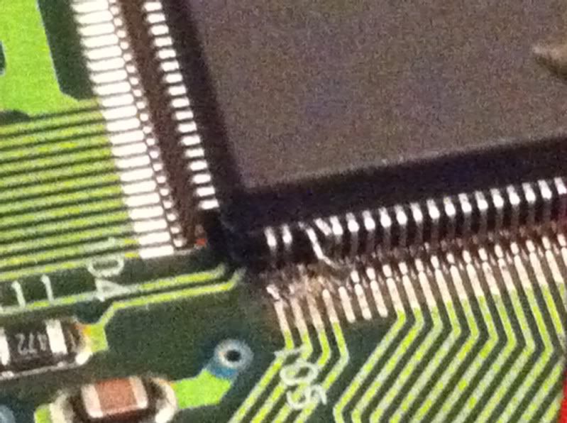
I think those two legs are the problem. The pic shows them after I pushed them back but I think they became disconnected anyway. 108 is just bent I botched the shit out of this. I followed the traces and sure enough they both go to controller port one. To make matters worse when I peeled the tape the +5v point for leg 107 came up and got screwed up I think I would need to go to to the underside of that point. I have decided to scrap this because I really don't have the skill to fix this and I'm really frustrated. If I can get another extra console I may try again sometime. Apparently 3rd time isn't a charm because my first 2 mods were successful.

  18. #18
    Pretzel (Level 4) APE992's Avatar
    Join Date
    Jun 2007
    Location
    Chico, CA
    Posts
    999
    Thanks Thanks Given 
    0
    Thanks Thanks Received 
    0
    Thanked in
    0 Posts
    Xbox LIVE
    APE992

    Default

    Doesn't look too difficult to fix honestly. Little dremel tool time to the casing and some fine soldering.
    I fix things. You name it, I'll work on it. Want something modded? Recapped?

  19. #19
    Alex (Level 15) InsaneDavid's Avatar
    Join Date
    Nov 2004
    Location
    Silicon Valley, USA
    Posts
    7,366
    Thanks Thanks Given 
    24
    Thanks Thanks Received 
    13
    Thanked in
    12 Posts

    Default

    That's one of the reasons I usually keep away from 315-XXXX and instead pick up the connection to it where it connects to a +5v plain via a through-hole. I isolate the through-hole from the +5v plain on the underside of the board by cutting a square around the through-hole in the +5v plain to isolate it. Then I use the through-hole on the top of the board as the connection point for pin 107. +5v and GND can be picked up anywhere they are available and of course there are many board revisions which may relocate said through-hole. Lifting pin 107 isn't a huge deal but back when I was modding a lot of Genesis 2 consoles, isolating the through-hole was my preferred way to take care of the setup.

    Kinda hard to see since I don't have a great picture of it, but here's one of the modded systems, the green wire is running to the isolated through-hole...


    SOME Model 1 systems make it much more straight forward with a series of four jumpers that have to be isolated and then have the switches wired in (lower right corner where the wires come from)...


    The other connections in both are for RCA jacks for audio / video.

    Also, using hot glue to tack wires into position on the PCB so they won't wiggle around and possibly tear out your connections is a good idea.
    Last edited by InsaneDavid; 05-11-2011 at 01:14 AM.

  20. #20
    Strawberry (Level 2) Lanzo's Avatar
    Join Date
    Apr 2010
    Location
    Youngstown, OH
    Posts
    442
    Thanks Thanks Given 
    0
    Thanks Thanks Received 
    0
    Thanked in
    0 Posts
    Xbox LIVE
    DT Maniac

    Default

    Who wants my failure?

Similar Threads

  1. Replies: 2
    Last Post: 09-21-2012, 08:17 PM
  2. JVC X'Eye with CD Region, Cart Region, and S-Video Mod
    By electrochip in forum Technical and Restoration Society
    Replies: 15
    Last Post: 03-04-2010, 02:33 AM
  3. JVC X'Eye with CD Region, Cart Region, and S-Video Mod
    By electrochip in forum Buying and Selling
    Replies: 0
    Last Post: 02-23-2010, 06:01 PM
  4. NES: Region locked controllers, change region?
    By Snigel in forum Technical and Restoration Society
    Replies: 2
    Last Post: 06-14-2008, 04:07 PM
  5. Various Wants - PSX, N64, Genny, 32X
    By tholly in forum Buying and Selling
    Replies: 5
    Last Post: 01-08-2007, 08:22 PM

Posting Permissions

  • You may not post new threads
  • You may not post replies
  • You may not post attachments
  • You may not edit your posts
  •